Chapter 6: Exemplar Implementation
The steps we’ve taken in the previous chapters to virtualize, disaggregate, optimize, distribute, and slice the cellular network not only help us understand the inner-workings of 5G, but they are also necessary to reduce the entirety of the 5G cellular network to practice. The goal is an implementation, which by definition, forces us to make specific engineering choices. This chapter describes one set of engineering choices that results in a running system. It should be interpreted as an exemplar, for the sake of completeness, but not the only possibility.
The system we describe is called CORD, which you will recall from the Introduction is an acronym (Central Office Re-architected as a Datacenter). More concretely, CORD is a blueprint for building a 5G deployment from commodity hardware and a collection of open source software components. We call this hardware/software combination a CORD POD, where the idea is to deploy a POD at each edge site that is part of a cellular network. The following describes CORD in terms of a set of engineering decisions. It is not a substitute for detailed documentation for installing, developing, and operating CORD, which can be found elsewhere: https://guide.opencord.org.
Note
As discussed in the Introduction, even though CORD includes “Central Office” in its name, a CORD POD is a general design, and not strictly limited to being deployed in a conventional Central Office.
Before getting into the specifics, it is important to understand that CORD is a work-in-progress, with a sizable open source community contributing to its code base. Many of the components are quite mature, and currently running in operator trials and production networks. Others (largely corresponding to the advanced capabilities described in the previous chapter) are prototypes that run in “demonstration mode,” but are not yet complete enough to be included in official releases. Also, as outlined in the earlier discussion on deployment options, CORD starts with a production-quality EPC that is being incrementally evolved into its 5G counterpart. (This chapter uses the EPC-specific components for illustrative purposes.)
6.1 Framework
Figure 6.1 gives a schematic overview of a CORD POD. It connects downstream to a set of DUs (and associated RUs), and upstream to the rest of the Internet. Internally, it includes a set of commodity servers (the figure shows four racks of three servers each, but the design accommodates anywhere from a partial rack to 16 racks) and a set of white-box switches arranged in a leaf-spine topology (the figure shows two leaves and two spine switches, but the design allows anywhere from a single switch to two leaf switches per rack and as many spine switches as necessary to provide sufficient east-to-west bandwidth).
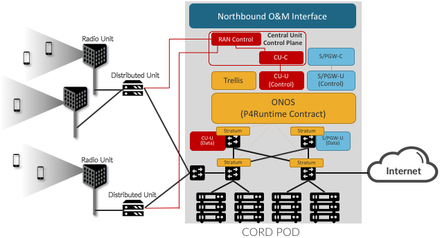
Figure 6.1: CORD implementation of RAN and Mobile Core.
With respect to software, Figure 6.1 shows a combination of RAN (red) and Mobile Core (blue) components, plus the modules that define the CORD platform (orange). We describe the platform components later in this chapter, but you can think of them as collectively implementing a multi-tenant cloud on top of which many different scalable services can run. The RAN and Mobile Core are two such tenants. The CORD platform can also host other edge services (which is one reason CORD is built using cloud technology in the first place), but exactly what other edge services might run on a given CORD POD is beyond the scope of this book.
The RAN and Core related components are ones we’ve described in earlier chapters. They include the Control and User planes of the CU and Mobile Core, respectively, where to simplify the diagram, we show the SGW and PGW merged into a single S/PGW. One aspect of Figure E that requires further elaboration is how each of the RAN and Mobile Core components are actually realized. There are three different manifestations of the functional components implied by the Figure: (1) the data plane layer of the CU-U and S/PGW-U are realized as P4 programs loaded into the programmable switches; (2) the control plane layer of the CU-U and S/PGW-U (as well as the Trellis platform module) are realized as control applications loaded onto the ONOS Network OS; and the remaining components are realized as Kubernetes-managed microservices. (Kubernetes is implicit, and not shown in the figure.)
To expand on this idea, Figure 6.2 gives an alternative view of a CORD POD, abstracting away the details of what services it hosts, and focusing instead on how those services are instantiated on the POD. In this figure, all the functionality instantiated onto the POD runs as a combination of Kubernetes-based microservices and ONOS-based control applications.
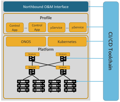
Figure 6.2: Alternative view of CORD, with a CI/CD toolchain managing the platform and set of services implemented by a combination of ONOS-based control apps and Kubernetes-based microservices.
When abstracted in this way, we can view a POD as including three major subsystems:
- Platform: The base layer common to all configurations includes Kubernetes as the container management system and ONOS as the SDN controller, with Stratum loaded on to each switch. Both ONOS and the control applications it hosts run as a Kubernetes-managed microservices.
- Profile: The deployment-specific collection of microservices and SDN control apps that have been selected to run on a particular POD. This is a variable and evolvable set, and it includes the control plane and edge services described elsewhere.
- CI/CD Toolchain: Used to assemble, deploy, operate, and upgrade a particular Platform/Profile combination. It implements a set of processes that transforms a collection of disaggregated and virtualized components into an operational system capable of responding to operator directives and carrying live traffic.
Although beyond the scope of this book, the CI/CD toolchain uses standard DevOps tools to bootstrap software onto the cluster of servers and switches, and rollout/rollback individual microservices and control applications. It also auto-generates the Northbound Interface (NBI) that operators use to manage the POD, based on a declarative specification of the Profile the POD is configured to support. This NBI is sufficiently complete to operate a CORD POD in a production environment.
6.2 Platform Components
We now return to the three platform-related components shown in Figures :ref:`Figure 6.1 <fig-cord> and 6.2. Each is a substantial open source component in its own right, but for our purposes, it is enough to understand the role each plays in supporting a 5G-based profile of CORD.
- Stratum: A thin operating system that runs locally on each white-box switch. It’s purpose is to provide a hardware-independent interface for managing and programming the switches in CORD. This includes using P4 to define the forwarding behavior of the switch’s forwarding pipeline (think of this program as a contract between the control and data planes), and P4Runtime to control that forwarding contract at runtime.
- ONOS: A Network Operating System used to configure and control a network of programmable white-box switches. It runs off-switch as a logically centralized SDN controller, and hosts a collection of SDN control applications, each of which controls some aspect of the underlying network. Because it is logically centralized, ONOS is designed to be highly available and to have scalable performance.
- Trellis: An ONOS-hosted SDN control application that implements a leaf-spine fabric on a network of white-box switches. It implements the control plane for several features, including VLANs and L2 bridging, IPv4 and IPv6 unicast and multicast routing, DHCP L3 relay, dual-homing of servers and upstream routers, QinQ forwarding/termination, MPLS pseudowires, and so on. In addition, Trellis can make the entire fabric appear as a single (virtual) router to upstream routers, which communicate with Trellis using standard BGP.
Stratum (running on each switch) and ONOS (running off-switch and managing a network of switches) communicate using the following interfaces:
- P4: Defines the forwarding behavior for programmable switching chips as well as model fixed-function ASIC pipelines. A P4 program defines a contract that is implemented by the data plane and programmable by the control plane.
- P4Runtime: An SDN-ready interface for controlling forwarding behavior at runtime. It is the key for populating forwarding tables and manipulating forwarding state, and it does so in a P4 program and hardware agnostic way.
- OpenConfig Models: Define a base for device configuration and management. These models can be programmatically extended for platform-specific functionality, but the goal is to minimize model deviations so as to enable a vendor-agnostic management plane.
- gNMI (gRPC Network Management Interface): Improves on the existing configuration interfaces by using a binary representation on the wire and enabling bi-directional streaming. Paired with the OpenConfig models, gNMI is SDN-ready.
- gNOI (gRPC Network Operations Interfaces): A collection of microservices that enable switch specific operations, like certificate management, device testing, software upgrade, and networking troubleshooting. gNOI provides a semantically rich API that replaces existing CLI-based approaches.
Trellis, as an SDN control application running on top of ONOS, controls packet forwarding across the switching fabric internal to a CORD POD (i.e., within a single site). But Trellis can also be extended across multiple sites deeper into the network using multiple stages of spines, as shown in Figure 6.3. This means Trellis has the potential to play a role in implementing the backhaul and midhaul network for the RAN, or alternatively, extending the RAN into customer premises (denoted “On Site” in the figure).
Figure 6.3: Trellis control application managing a (possibly distributed) leaf-spine fabric.