Chapter 3: Basic Architecture
This chapter identifies the main architectural components of cellular access networks. It focuses on the components that are common to both 4G and 5G, and as such, establishes a foundation for understanding the advanced features of 5G presented in later chapters.
This overview is partly an exercise in introducing 3GPP terminology. For someone that is familiar with the Internet, this terminology can seem arbitrary (e.g., “eNB” is a “base station”), but it is important to keep in mind that this terminology came out of the 3GPP standardization process, which has historically been concerned about telephony and almost completely disconnected from the IETF and other Internet-related efforts. To further confuse matters, the 3GPP terminology often changes with each generation (e.g., a base station is called eNB in 4G and gNB in 5G). We address situations like this by using generic terminology (e.g., base station), and referencing the 3GPP-specific counterpart only when the distinction is helpful.
Note
This example is only the tip of the terminology iceberg. For a slightly broader perspective on the complexity of terminology in 5G, see Marcin Dryjanski’s blog post.
3.1 Main Components
The cellular network provides wireless connectivity to devices that are on the move. These devices, which are known as User Equipment (UE), have until recently corresponded to smartphones and tablets, but will increasingly include cars, drones, industrial and agricultural machines, robots, home appliances, medical devices, and so on.
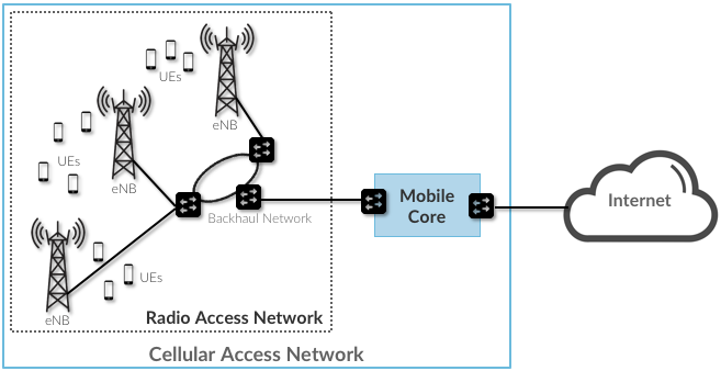
Figure 3.1: Cellular networks consists of a Radio Access Network (RAN) and a Mobile Core.
As shown in Figure 3.1, the cellular network consists of two main subsystems: the Radio Access Network (RAN) and the Mobile Core. The RAN manages the radio spectrum, making sure it is both used efficiently and meets the quality-of-service requirements of every user. The main component in the RAN is the crypticly named eNodeB (or eNB), which is short for the equally cryptic evolved Node B. The Mobile Core is a bundle of functionality (as opposed to a device) that serves several purposes:
- Provides Internet (IP) connectivity for both data and voice services.
- Ensures this connectivity fulfills the promised QoS requirements.
- Tracks user mobility to ensure uninterrupted service.
- Tracks subscriber usage for billing and charging.
Note
Mobile Core is another example of a generic term. In 4G this is called the Evolved Packet Core (EPC) and in 5G it is called the Next Generation Core (NG-Core).
Even though the word “Core” is in its name, from an Internet perspective, the Mobile Core is still part of the access network, effectively providing a bridge between the RAN and the IP-world.
Taking a closer look at Figure 3.1, we see that a Backhaul Network interconnects the eNBs that implement the RAN with the Mobile Core. This network is typically wired, may or may not have the ring topology shown in the Figure, and is often constructed from commodity components found elsewhere in the Internet. For example, the Passive Optical Network (PON) that implements Fiber-to-the-Home is a prime candidate for implementing the RAN backhaul. The backhaul network is obviously a necessary part of the RAN, but it is an implementation choice and not prescribed by the 3GPP standard.
Although 3GPP specifies all the elements that implement the RAN and Mobile Core in an open standard—including sub-layers we have not yet introduced—network operators have historically bought proprietary implementations of each subsystem from a single vendor. This lack of an open source implementation contributes to the perceived “opaqueness” of the cellular network in general, and the RAN in particular. And while it is true that an eNodeB implementation does contain sophisticated algorithms for scheduling transmission on the radio spectrum—algorithms that are considered valuable Intellectual Property of the equipment vendors—there is significant opportunity to open and disaggregate both the RAN and the Mobile Core. The following two sections describe each, in turn.
Before getting to those details, Figure 3.2 redraws components from Figure 3.1 to highlight two important distinctions. The first is that the eNB (which we will refer to as the Base Station from here on) has an analog component (depicted by an antenna) and a digital component (depicted by a processor). The second is that the Mobile Core is partitioned into a Control Plane and User Plane, which is similar to the control/data plane split that someone familiar with the Internet would recognize. (3GPP also recently introduced a corresponding acronym—CUPS, Control and User Plane Separation—to denote this idea). The importance of these two distinctions will become clear in the following discussion.
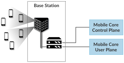
Figure 3.2: Mobile Core divided into a Control Plan and a User Plane, an architectural feature known as CUPS: Control and User Plane Separation
3.2 Radio Access Network
We now describe the RAN by sketching the role each base station plays. Keep in mind this is kind of like describing the Internet by explaining how a router works—a not unreasonable place to start, but it doesn’t fully do justice to the end-to-end story.
First, each base station establishes the wireless channel for a subscriber’s UE upon power-up or upon handover when the UE is active. This channel is released when the UE remains idle for a predetermined period of time. Using 3GPP terminology, this wireless channel is said to provide a bearer service.
Note
The term “bearer” has historically been used in telecommunications (including early wireline technologies like ISDN) to denote “data,” as opposed to a channel that carries “signalling” information.
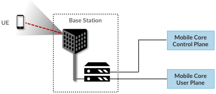
Figure 3.3: Base Station detects (and connects to) active UEs.
Second, each base station establishes ”3GPP Control Plane” connectivity between the UE and the corresponding Mobile Core Control Plane component, and forwards signaling traffic between the two. This signaling traffic enables UE authentication, registration, mobility tracking.
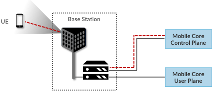
Figure 3.4: Base Station establishes control plane connectivity between each UE and the Mobile Core.
Third, for each active UE, the base station establishes one or more tunnels between the corresponding Mobile Core User Plane component.
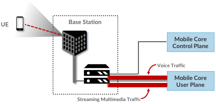
Figure 3.5: Base station establishes one or more tunnels between each UE and the Mobile Core’s User Plane.
Fourth, the base station forwards both control and user plane packets between the Mobile Core and the UE. These packets are tunnelled over SCTP/IP and GTP/UDP/IP, respectively. SCTP (Stream Control Transport Protocol) is 3GPP-defined alternative to TCP, tailored to carry signalling (control) information for telephony services. GTP (a nested acronym corresponding to (General Packet Radio Service) Tunneling Protocol) is a 3GPP-specific tunneling protocol designed to run over UDP.
As an aside, it is noteworthy that connectivity between the RAN and the Mobile Core is IP-based. This was introduced as one of the main changes between 3G and 4G. Prior to 4G, the internals of the cellular network were circuit-based, which is not surprising given its origins as a voice network.
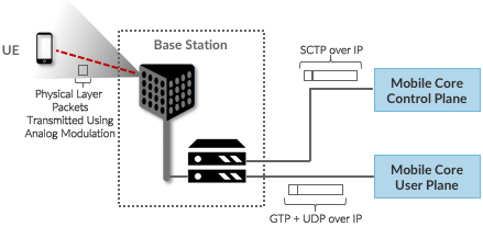
Figure 3.6: Base Station to Mobile Core (and Base Station to Base Station) control plane tunneled over SCTP/IP and user plane tunneled over GTP/UDP/IP.
Fifth, the base station coordinates UE handovers between neighboring base stations, using direct station-to-station links. Exactly like the station-to-core connectivity shown in the previous figure, these links are used to transfer both control plane (SCTP over IP) and user plane (GTP over UDP/IP) packets.
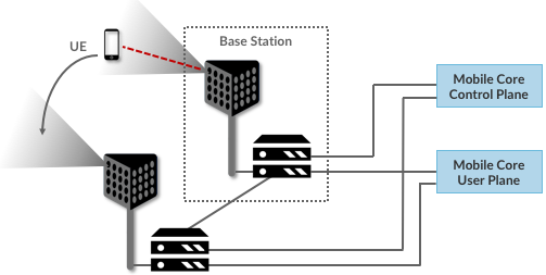
Figure 3.7: Base Stations cooperate to implement UE hand over.
Sixth, the base station coordinates wireless multi-point transmission to a UE from multiple base stations, which may or may not be part of a UE handover from one base station to another.
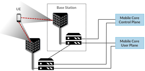
Figure 3.8: Base Stations cooperate to implement multipath transmission (link aggregation) to UEs.
For our purposes, the main takeaway is that the base station can be viewed as a specialized forwarder. In the Internet-to-UE direction, it fragments outgoing IP packets into physical layer segments and schedules them for transmission over the available radio spectrum, and in the UE-to-Internet direction it assembles physical layer segments into IP packets and forwards them (over a GTP/UDP/IP tunnel) to the upstream user plane of the Mobile Core. Also, based on observations of the wireless channel quality and per-subscriber policies, it decides whether to (a) forward outgoing packets directly to the UE, (b) indirectly forward packets to the UE via a neighboring base station, or (c) utilize multiple paths to reach the UE. The third case has the option of either spreading the physical payloads across multiple base stations or across multiple carrier frequencies of a single base station (including Wi-Fi).
Note that as outlined in the previous chapter, scheduling is complex and multi-faceted, even when viewed as a localized decision at a single base station. What we now see is that there is also a global element, whereby it’s possible to forward traffic to a different base station (or to multiple base stations) in an effort to make efficient use of the radio spectrum over a larger geographic area.
In other words, the RAN as a whole (i.e., not just a single base station) not only supports handovers (an obvious requirement for mobility), but also link aggregation and load balancing, mechanisms that are familiar to anyone that understands the Internet. We will revisit how such RAN-wide (global) decisions can be made using SDN techniques in a later chapter.
3.3 Mobile Core
The main function of the Mobile Core is to provide external packet data network (e.g., Internet) connectivity to mobile subscribers, while ensuring that they are authenticated and their observed service qualities satisfy their subscription SLAs. An important aspect of the Mobile Core is that it needs to manage all subscribers’ mobility by keeping track of their last whereabouts at the granularity of the serving base station.
While the aggregate functionality remains largely the same as we migrate from 4G to 5G, how that functionality is virtualized and factored into individual components changes, with the 5G Mobile Core heavily influenced by the cloud’s march towards a microservice-based (cloud native) architecture. This shift to cloud native is deeper than it might first appear, in part because it opens the door to customization and specialization. Instead of supporting just voice and broadband connectivity, the 5G Mobile Core can evolve to also support, for example, massive IoT, which has a fundamentally different latency requirement and usage pattern (e.g., many more devices connecting intermittently). This stresses—if not breaks—a one-size-fits-all approach to session management.
4G Mobile Core
The 4G Mobile Core, which 3GPP officially refers to as the Evolved Packet Core (EPC), consists of five main components, the first three of which run in the Control Plane (CP) and the second two of which run in the User Plane (UP):
- MME (Mobility Management Entity): Tracks and manages the movement of UEs throughout the RAN. This includes recording when the UE is not active.
- HSS (Home Subscriber Server): A database that contains all subscriber-related information.
- PCRF (Policy & Charging Rules Function): Tracks and manages policy rules and records billing data on subscriber traffic.
- SGW (Serving Gateway): Forwards IP packets to and from the RAN. Anchors the Mobile Core end of the bearer service to a (potentially mobile) UE, and so is involved in handovers from one base station to another.
- PGW (Packet Gateway): Essentially an IP router, connecting the Mobile Core to the external Internet. Supports additional access-related functions, including policy enforcement, traffic shaping, and charging.
Although specified as distinct components, in practice the SGW (RAN-facing) and PGW (Internet-facing) are often combined in a single device, commonly referred to as an S/PGW. The end result is illustrated in Figure 3.9.
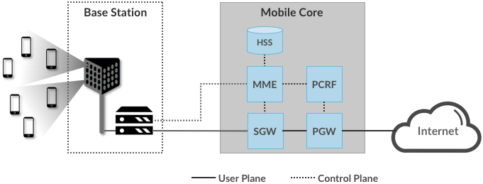
Figure 3.9: 4G Mobile Core (Evolved Packet Core).
Note that 3GPP is flexible in how the Mobile Core components are deployed to serve a geographic area. For example, a single MME/PGW pair might serve a metropolitan area, with SGWs deployed across ~10 edge sites spread throughout the city, each of which serves ~100 base stations. But alternative deployment configurations are allowed by the spec.
5G Mobile Core
The 5G Mobile Core, which 3GPP calls the NG-Core, adopts a microservice-like architecture, where we say “microservice-like” because while the 3GPP specification spells out this level of disaggregation, it is really just prescribing a set of functional blocks and not an implementation. Keeping in mind a set of functional blocks is very different from the collection of engineering decisions that go into designing a microservice-based system, viewing the collection of components shown in Figure 3.10 as a set of microservices is a good working model.
The following organizes the set of functional blocks into three groups. The first group runs in the Control Plane (CP) and has a counterpart in the EPC:
- AMF (Core Access and Mobility Management Function): Manages the mobility-related aspects of the EPC’s MME. Responsible for connection and reachability management, mobility management, access authentication and authorization, and location services.
- SMF (Session Management Function): Manages each UE session, including IP address allocation, selection of associated UP function, control aspects of QoS, and control aspects of UP routing. Roughly corresponds to part of the EPC’s MME and the control-related aspects of the EPC’s PGW.
- PCF (Policy Control Function): Manages the policy rules that other CP functions then enforce. Roughly corresponds to the EPC’s PCRF.
- UDM (Unified Data Management): Manages user identity, including the generation of authentication credentials. Includes part of the functionality in the EPC’s HSS.
- AUSF (Authentication Server Function): Essentially an authentication server. Includes part of the functionality in the EPC’s HSS.
The second group also runs in the Control Plane (CP) but does not have a counterpart in the EPC:
- SDSF (Structured Data Storage Network Function): A “helper” service used to store structured data. Might be implemented by an “SQL Database” in a microservices-based system.
- UDSF (Unstructured Data Storage Network Function): A “helper” service used to store unstructured data. Might be implemented by a “Key/Value Store” in a microservices-based system.
- NEF (Network Exposure Function): A means to expose select capabilities to third-party services, including translation between internal and external representations for data. Might be implemented by an “API Server” in a microservices-based system.
- NFR (NF Repository Function): A means to discover available services. Might be implemented by a “Discovery Service” in a microservices-based system.
- NSSF (Network Slicing Selector Function): A means to select a Network Slice to serve a given UE. Network slices are essentially a way to differentiate service given to different users. It is a key feature of 5G that we discuss in depth later in this tutorial.
The third group includes the one component that runs in the User Plane (UP):
- UPF (User Plane Function): Forwards traffic between RAN and the Internet, corresponding to the S/PGW combination in EPC. In addition to packet forwarding, responsible for policy enforcement, lawful intercept, traffic usage reporting, and QoS policing.
Of these, the first and third groups are best viewed as a straightforward refactoring of 4G’s EPC, while the second group—despite the gratuitous introduction of new terminology—is 3GPP’s way of pointing to a cloud native solution as the desired end-state for the Mobile Core. Of particular note, introducing distinct storage services means that all the other services can be stateless, and hence, more readily scalable. Also note that Figure 3.10 adopts an idea that’s common in microservice-based systems, namely, to show a “message bus” interconnecting all the components rather than including a full set of pairwise connections. This also suggests a well-understood implementation strategy.
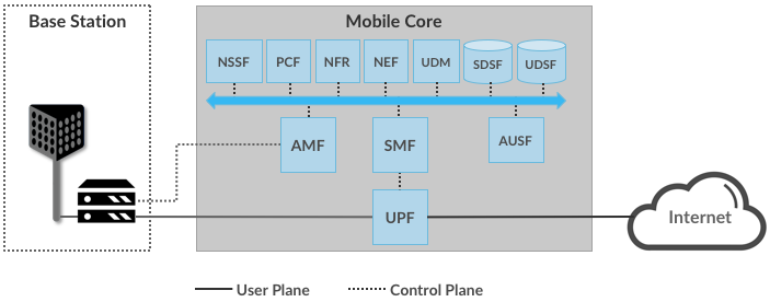
Figure 3.10: 5G Mobile Core (NG-Core).
Stepping back from these details, and with the caveat that we are presuming an implementation, the main takeaway is that we can conceptualize the Mobile Core as a Service Mesh. We adopt this terminology for “an interconnected set of microservices” since it is widely used in cloud native systems. Other terms you will sometimes hear are Service Graph and Service Chain, the latter being more prevalent in NFV-oriented documents. 3GPP is silent on the specific terminology since it is considered an implementation choice rather than part of the specification.
3.4 Deployment Options
With an already deployed 4G RAN/EPC in the field and a new 5G RAN/NG-Core deployment underway, we can’t ignore the issue of transitioning from 4G to 5G (an issue the IP-world has been grappling with for 20 years). 3GPP officially spells out multiple deployment options, which can be summarized as follows:
- Stand-Alone 4G / Stand-Alone 5G
- Non-Stand-Alone (4G+5G RAN) over 4G’s EPC
- Non-Stand-Alone (4G+5G RAN) over 5G’s NG-Core
Focusing on the second pair, which imply incremental phasing, we see two general strategies. The first is to connect new 5G base stations to existing 4G-based EPCs, and then incrementally evolve the Mobile Core by refactoring the components and adding NG-Core capabilities over time. The second is to implement a backward-compatible NG-Core that can support both 4G and 5G base stations, where the new NG-Core could be implemented from scratch, but would likely start with the existing EPC code base.
One reason we call attention to the phasing issue is that we face a similar challenge in the chapters that follow. The closer the following discussion gets to implementation details, the more specific we have to be about whether we are using 4G components or 5G components. As a general rule, we use 4G components—particularly with respect to the Mobile Core, since that’s the available open source software—and trust the reader can make the appropriate substitution without loss of generality. Like the broader industry, the open source community is in the process of incrementally evolving its 4G code base into its 5G-compliant counterpart.