3.4 Implementation
So far, we have talked about what switches and routers must do without describing how they do it. There is a straightforward way to build a switch or router: Buy a general-purpose processor and equip it with multiple network interfaces. Such a device, running suitable software, can receive packets on one of its interfaces, perform any of the switching or forwarding functions described in this chapter, and send packets out another of its interfaces. This so called software switch is not too far removed from the architecture of many commercial mid- to low-end network devices. Implementations that deliver high-end performance typically take advantage of additional hardware acceleration. We refer to these as hardware switches, although both approaches obviously include a combination of hardware and software.
This section gives an overview of both software-centric and hardware-centric designs, but it is worth noting that on the question of switches versus routers, the distinction isn’t such a big deal. It turns out that the implementation of switches and routers have so much in common that a network administrator typically buys a single forwarding box and then configures it to be an L2 switch, an L3 router, or some combination of the two. Since their internal designs are so similar, we’ll use the word switch to cover both variants throughout this section, avoiding the tedium of saying “switch or router” all the time. We’ll call out the differences between the two when appropriate.
Software Switch
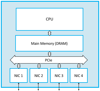
Figure 93 shows a software switch built using a general-purpose processor with four network interface cards (NICs). The path for a typical packet that arrives on, say, NIC 1 and is forwarded out on NIC 2 is straightforward: as NIC 1 receives the packet it copies its bytes directly into the main memory over the I/O bus (PCIe in this example) using a technique called direct memory access (DMA). Once the packet is in memory, the CPU examines its header to determine which interface the packet should be sent out on, and instructs NIC 2 to transmit the packet, again directly out of main memory using DMA. The important take-away is that the packet is buffered in main memory (this is the “store” half of store-and-forward), with the CPU reading only the necessary header fields into its internal registers for processing.
There are two potential bottlenecks with this approach, one or both of which limits the aggregate packet forwarding capacity of the software switch.
The first problem is that performance is limited by the fact that all packets must pass into and out of main memory. Your mileage will vary based on how much you are willing to pay for hardware, but as an example, a machine limited by a 1333-MHz, 64-bit-wide memory bus can transmit data at a peak rate of a little over 100 Gbps—enough to build a switch with a handful of 10-Gbps Ethernet ports, but hardly enough for a high-end router in the core of the Internet.
Moreover, this upper bound assumes that moving data is the only problem. This is a fair approximation for long packets but a bad one when packets are short, which is the worst-case situation switch designers have to plan for. With minimum-sized packets, the cost of processing each packet—parsing its header and deciding which output link to transmit it on—is likely to dominate, and potentially become a bottleneck. Suppose, for example, that a processor can perform all the necessary processing to switch 40 million packets each second. This is sometimes called the packet per second (pps) rate. If the average packet is 64 bytes, this would imply
Throughput = pps x BitsPerPacket
that is, a throughput of about 20 Gbps—fast, but substantially below the range users are demanding from their switches today. Bear in mind that this 20 Gbps would be shared by all users connected to the switch, just as the bandwidth of a single (unswitched) Ethernet segment is shared among all users connected to the shared medium. Thus, for example, a 16-port switch with this aggregate throughput would only be able to cope with an average data rate of about 1 Gbps on each port.[*]
| [*] | These example performance numbers do not represent the absolute maximum throughput rate that highly tuned software running on a high-end server could achieve, but they are indicative of limits one ultimately faces in pursuing this approach. |
One final consideration is important to understand when evaluating switch implementations. The non-trivial algorithms discussed in this chapter—the spanning tree algorithm used by learning bridges, the distance-vector algorithm used by RIP, and the link-state algorithm used by OSPF—are not directly part of the per-packet forwarding decision. They run periodically in the background, but switches do not have to execute, say, OSPF code for every packet it forwards. The most costly routine the CPU is likely to execute on a per-packet basis is a table lookup, for example, looking up a VCI number in a VC table, an IP address in an L3 forwarding table, or an Ethernet address in an L2 forwarding table.
Key Takeaway
The distinction between these two kinds of processing is important enough to give it a name: the control plane corresponds to the background processing required to “control” the network (e.g., running OSPF, RIP, or the BGP protocol described in the next chapter) and the data plane corresponds to the per-packet processing required to move packets from input port to output port. For historical reasons, this distinction is called control plane and user plane in cellular access networks, but the idea is the same, and in fact, the 3GPP standard defines CUPS (Control/User Plane Separation) as an architectural principle.
These two kinds of processing are easy to conflate when both run on the same CPU, as is the case in software switch depicted in Figure 93, but performance can be dramatically improved by optimizing how the data plane is implemented, and correspondingly, specifying a well-defined interface between the control and data planes.
Hardware Switch
Throughout much of the Internet’s history, high-performance switches and routers have been specialized devices, built with Application-Specific Integrated Circuits (ASICs). While it was possible to build low-end routers and switches using commodity servers running C programs, ASICs were required to achieve the required throughput rates.
The problem with ASICs is that hardware takes a long time to design and fabricate, meaning the delay for adding new features to a switch is usually measured in years, not the days or weeks today’s software industry is accustomed to. Ideally, we’d like to benefit from the performance of ASICs and the agility of software.
Fortunately, recent advances in domain specific processors (and other commodity components) have made this possible. Just as importantly, the full architectural specification for switches that take advantage of these new processors is now available on-line—the hardware equivalent of open source software. This means anyone can build a high-performance switch by pulling the blueprint off the web (see the Open Compute Project, OCP, for examples) in the same way it is possible to build your own PC. In both cases you still need software to run on the hardware, but just as Linux is available to run on your home-built PC, there are now open source L2 and L3 stacks available on GitHub to run on your home-built switch. Alternatively, you can simply buy a pre-built switch from a commodity switch manufacturer and then load your own software onto it. The following describes these open white-box switches, so called to contrast them with closed “black-box” devices that have historically dominated the industry.
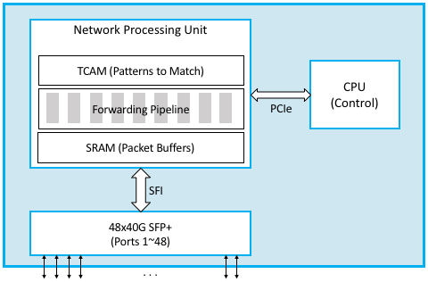
Figure 94 is a simplified depiction of a white-box switch. The key difference from the earlier implementation on a general-purpose processor is the addition of a Network Processor Unit (NPU), a domain-specific processor with an architecture and instruction set that has been optimized for processing packet headers (i.e., for implementing the data plane). NPUs are similar in spirit to GPUs that have an architecture optimized for rendering computer graphics, but in this case, the NPU is optimized for parsing packet headers and making a forwarding decision. NPUs are able to process packets (input, make a forwarding decision, and output) at rates measured in Terabits-per-second (Tbps), easily fast enough to keep up with 32x100-Gbps ports, or the 48x40-Gbps ports shown in the diagram.
The beauty of this new switch design is that a given white-box can now be programmed to be an L2 switch, and L3 router, or a combination of both, just by a matter of programming. The exact same control plane software stack used in a software switch still runs on the control CPU, but in addition, data plane “programs” are loaded onto the NPU to reflect the forwarding decisions made by the control plane software. Exactly how one “programs” the NPU depends on the chip vendor, of which there are currently several. In some cases, the forwarding pipeline is fixed and the control processor merely loads the forwarding table into the NPU (by fixed we mean the NPU only knows how to process certain headers, like Ethernet and IP), but in other cases, the forwarding pipeline is itself programmable. P4 is a new programming language that can be used to program such NPU-based forwarding pipelines. Among other things, P4 tries to hide many of the differences in the underlying NPU instruction sets.
Internally, an NPU takes advantage of three technologies. First, a fast
SRAM-based memory buffers packets while they are being processed. SRAM
(Static Random Access Memory), is roughly an order of magnitude faster
than the DRAM (Dynamic Random Access Memory) that is used by main
memory. Second, a TCAM-based memory stores bit patterns to be matched in
the packets being processed. The “CAM” in TCAM stands for “Content
Addressable Memory,” which means that the key you want to look up in a
table can effectively be used as the address into the memory that
implements the table. The “T” stands for “Ternary” which is a fancy way
to say the key you want to look up can have wildcards in it (e.g, key
10*1 matches both 1001 and 1011). Finally, the processing
involved to forward each packet is implemented by a forwarding pipeline.
This pipeline is implemented by an ASIC, but when well-designed, the
pipeline’s forwarding behavior can be modified by changing the program
it runs. At a high level, this program is expressed as a collection of
(Match, Action) pairs: if you match such-and-such field in the header,
then execute this-or-that action.
The relevance of packet processing being implemented by a multi-stage pipeline rather than a single-stage processor is that forwarding a single packet likely involves looking at multiple header fields. Each stage can be programmed to look at a different combination of fields. A multi-stage pipeline adds a little end-to-end latency to each packet (measured in nanoseconds), but also means that multiple packets can be processed at the same time. For example, Stage 2 can be making a second lookup on packet A while Stage 1 is doing an initial lookup on packet B, and so on. This means the NPU as a whole is able to keep up with line speeds. As of this writing, the state-of-the-art is 12.8 Tbps.
Finally, Figure 94 includes other commodity components that make this all practical. In particular, it is now possible to buy pluggable transceiver modules that take care of all the media access details—be it Gigabit Ethernet, 10-Gigabit Ethernet, or SONET—as well as the optics. These transceivers all conform to standardized form factors, such as SFP+, that can in turn be connected to other components over a standardized bus (e.g., SFI). Again, the key takeaway is that the networking industry is just now entering into the same commoditized world that the computing industry has enjoyed for the last two decades.
Software Defined Networks
With switches becoming increasingly commoditized, attention is rightfully shifting to the software that controls them. This puts us squarely in the middle of a trend to build Software Defined Networks (SDN), an idea that started to germinate about ten years ago. In fact, it was the early stages of SDN that triggered the networking industry to move towards white-box switches.
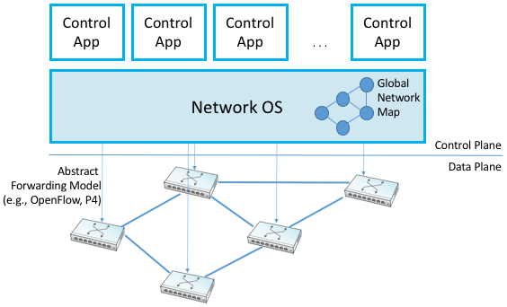
The fundamental idea of SDN is one we’ve already discussed: to decouple the network control plane (i.e., where routing algorithms like RIP, OSPF, and BGP run) from the network data plane (i.e., where packet forwarding decisions get made), with the former moved into software running on commodity servers and the latter implemented by white-box switches. The key enabling idea behind SDN was to take this decoupling a step further, and to define a standard interface between the control plane and the data plane. Doing so allows any implementation of the control plane to talk to any implementation of the data plane; this breaks the dependency on any one vendor’s bundled solution. The original interface is called OpenFlow, and this idea of decoupling the control and data planes came to be known as disaggregation. (The P4 language mentioned in the previous subsection is a second-generation attempt to define this interface by generalizing OpenFlow.)
Another important aspect of disaggregation is that a logically centralized control plane can be used to control a distributed network data plane. We say logically centralized because while the state collected by the control plane is maintained in a global data structure, such as a Network Map, the implementation of this data structure could still be distributed over multiple servers. For example, it could run in a cloud. This is important for both scalability and availability, where the key is that the two planes are configured and scaled independent of each other. This idea took off quickly in the cloud, where today’s cloud providers run SDN-based solutions both within their datacenters and across the backbone networks that interconnect their datacenters.
One consequence of this design that isn’t immediately obvious is that a logically centralized control plane doesn’t just manage a network of physical (hardware) switches that interconnects physical servers, but it also manages a network of virtual (software) switches that interconnect virtual servers (e.g., Virtual Machines and containers). If you’re counting “switch ports” (a good measure of all the devices connected to your network) then the number of virtual ports in the Internet rocketed past the number of physical ports in 2012.

Figure 95. Network Operating System (NOS) hosting a set of control applications and providing a logically centralized point of control for an underlying network data plane.
One of other key enablers for SDN’s success, as depicted in Figure 95, is the Network Operating System (NOS). Like a server operating system (e.g., Linux, iOS, Android, Windows) that provides a set of high-level abstractions that make it easier to implement applications (e.g., you can read and write files instead of directly accessing disk drives), a NOS makes it easier to implement network control functionality, otherwise known as Control Apps. A good NOS abstracts the details of the network switches and provides a Network Map abstraction to the application developer. The NOS detects changes in the underlying network (e.g., switches, ports, and links going up-and-down) and the control application simply implements the behavior it wants on this abstract graph. This means the NOS takes on the burden of collecting network state (the hard part of distributed algorithms like Link-State and Distance-Vector algorithms) and the app is free to simply implement the shortest path algorithm and load the forwarding rules into the underlying switches. By centralizing this logic, the goal is to come up with a globally optimized solution. The published evidence from cloud providers that have embraced this approach confirms this advantage.
As much of an advantage as the cloud providers have been able to get out of SDN, its adoption in enterprises and Telcos has been much slower. This is partly about the ability of different markets to manage their networks. The Googles, Microsofts, and Amazons of the world have the engineers and DevOps skills needed to take advantage of this technology, whereas others still prefer pre-packaged and integrated solutions that support the management and command line interfaces they are familiar with.

